By Dr. Ing Praveen Kumar
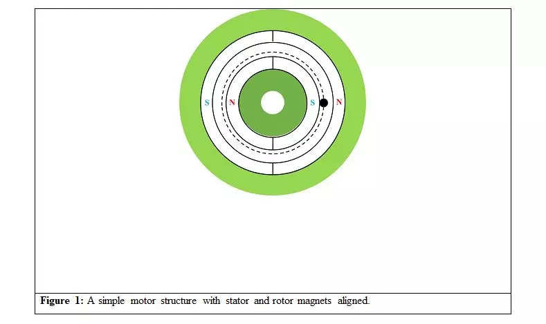
Within the third article, we began our dialogue on discipline weakening, utilizing a easy motor illustrated in Determine 1 to clarify the idea. We delved into the relative angle between the 2 units of poles (or magnets), which warrants additional examination. As talked about within the second article, a motor generates two varieties of torque: interplay torque and reluctance torque. Interplay torque necessitates two magnetic fields interacting within the air. Nonetheless, mere interplay will not be sufficient, and two further circumstances should be met to supply non-zero torque at a selected pace:
a. The stator and the rotor ought to have an equal variety of poles.
b. Each magnetic fields ought to rotate on the identical pace, that means the relative pace between them should be zero.
With these factors in thoughts, we revisit our dialogue on the relative angle between the magnetic fields. To attain a selected torque worth, we should keep a selected relative angle between the 2 magnetic fields at various speeds. The management algorithm’s accountability is to find out and keep this relative angle at totally different speeds. Nonetheless, for the algorithm to operate successfully, the motor should be controllable, which is set by its design. Within the earlier article, we analysed the connection between the relative angle of the 2 magnetic fields and the torque. This understanding aids in designing superior motors and suitable management algorithms.
To this point, we’ve seen we analysed the state of affairs the place the energy of the magnetic flux density produced by the stator () and the rotor (
) magnets was equal. Furthermore, we mentioned Maxwell’s stress tensor for torque calculation, and the salient factors of the method are:
a.For a given rotor place, decide the resultant radial and tangential flux density parts on a path within the air hole. It’s the dotted circle in Determine 1.
b.Decide the product of the 2 parts at each level of the dotted circle.
c.The torque is proportional to the sum of the values we get in step b.
At the moment we’ll search a solution to the query: What occurs when the stator and rotor magnets are not of equal energy?
To reply the above query, we will think about two instances:
Case 1: Each the stator and rotor and rotor contribute equally to the air hole flux density, i.e. . That is the case that we analysed within the earlier article.
Case 2: Stator’s contribution to the air hole magnetic flux density is lower than that of the rotor (), .i.e.
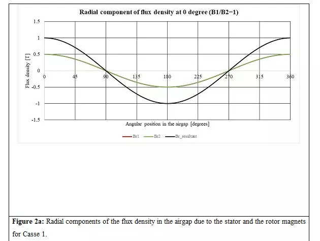
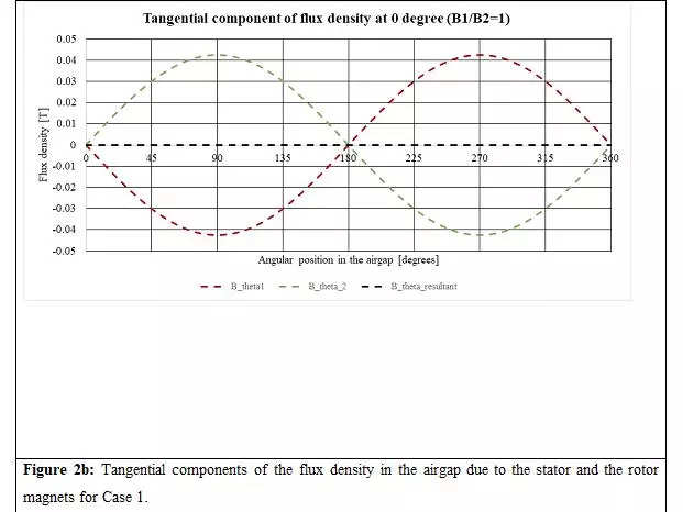
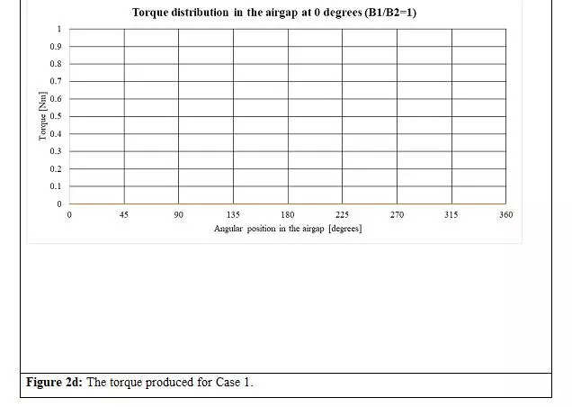
When analyzing Case 1 () at a displacement of 0 levels, as depicted in Determine 1, we are able to see the web radial and tangential parts in Figures 2a and 2b, respectively. The radial parts of the stator and rotor magnets are in part, possess equal magnitudes, and superimpose on one another. Conversely, the tangential parts have equal magnitudes however are 180 levels aside. In consequence, the resultant radial element peaks at 1T, whereas the resultant tangential element is zero. Determine 2c shows the resultant radial and tangential parts. As talked about within the third article, the generated torque straight correlates to the product of the resultant radial and tangential parts (Maxwell’s stress tensor) of the air hole flux densities. On this case, as proven in Determine second, the torque is zero.

All of the flux densities and torque for Case 2 () for the stator and the rotor orientations proven in Determine 1 are given in Figures 3a to 3d. The torque distribution within the air hole (Determine 3d) provides to zero.

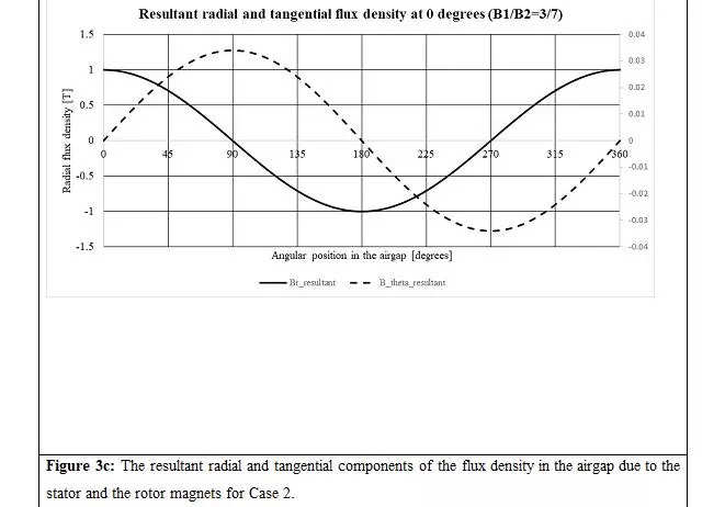
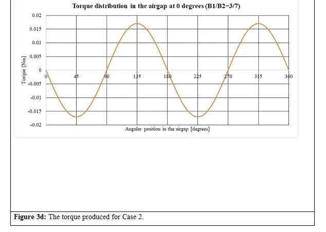
There are fascinating variations that we are able to see from the above set of figures:
a.The height of the resultant radial parts is similar for instances 1 and a pair of (Figures 2a and 3a)
b.In contrast to Case 1 (Determine 2b), the resultant tangential element will not be zero in Case 2 (Determine 3b) as a result of in Case 2, the magnitudes of the stator and rotor’s tangential parts will not be equal.
c.The online torque in each instances is zero.
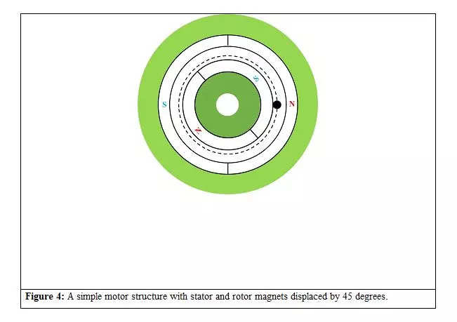
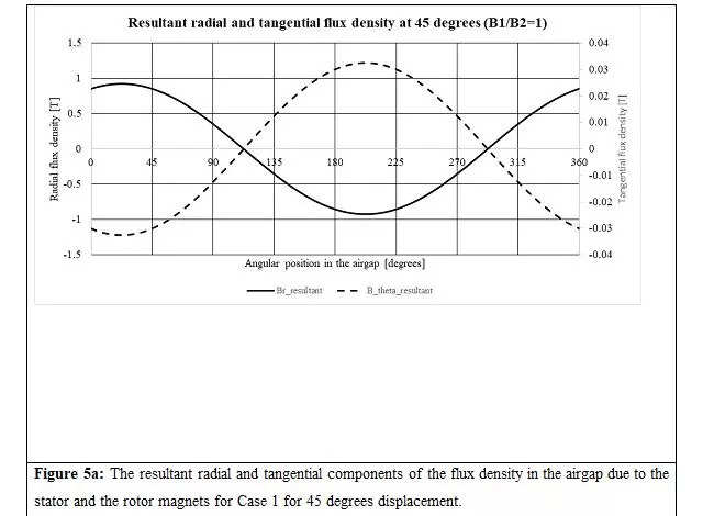
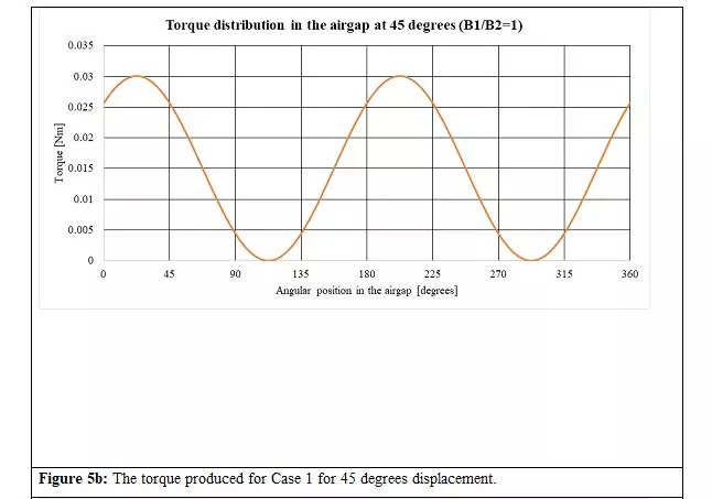
Now allow us to analyse the state of affairs when the stator and rotor magnets are displaced by 45 levels, as proven in Determine 4. The resultant radial and tangential parts of the airgap flux densities and torque distribution for Instances 1 and a pair of are proven in Figures 5a to 5d.
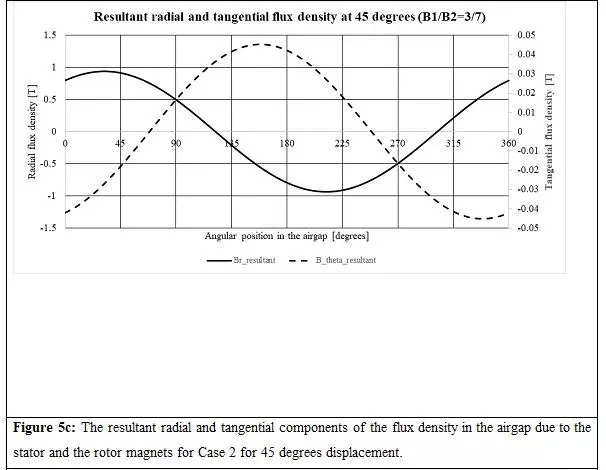
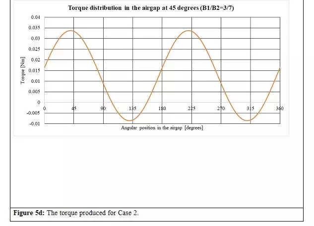
Equally, for 90-degree displacement between the magnets (Determine 6), the resultant radial and tangential parts of the airgap flux densities and torque distribution for Instances 1 and a pair of are proven in Figures 7a to 7d.

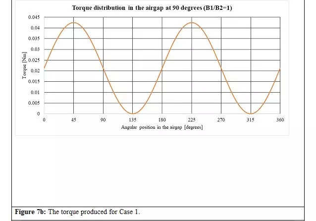
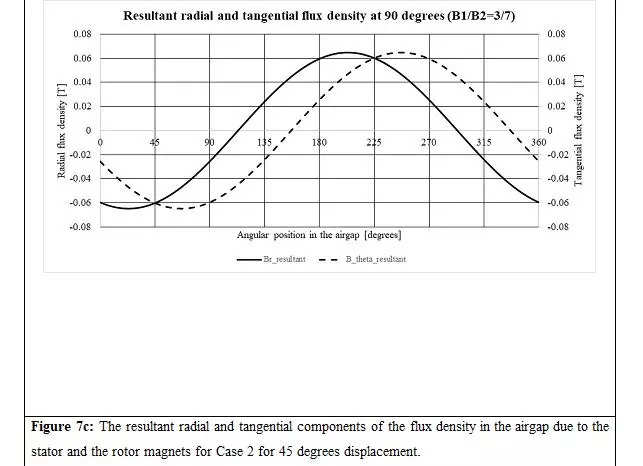
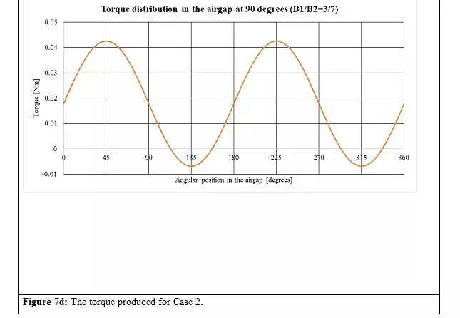
Some very profound insights are hidden in Figures 5 to 7, and they’re:
a.When , i.e., the stator and rotor’s magnetic fields are of equal energy, the resultant radial and tangential parts of the air hole flux densities have a part shift of 180 levels no matter the relative angle (Determine 5a, 6a and 7a).
b.Within the case (Determine 5c, 6c and 7c), the resultant radial and tangential parts of air hole flux densities don’t have a part shift of 180 levels. It modifications with the relative angle between the 2 units of poles. This assertion is true not just for
however typically for
.
c. Because of level a, the utmost torque is produced by a motor the place the stator and rotor magnetic fields are evenly balanced.
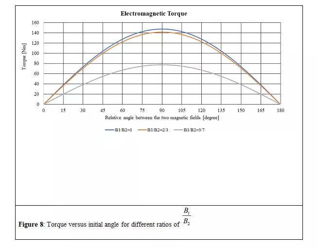
If we do the evaluation for various relative angles and magnetic discipline energy ratios (), we are able to get a whole spectrum of the torque versus load angle, as proven in Determine 8.
The evaluation and dialogue above spotlight an important side to think about through the design course of: A well-designed motor should have an equal contribution from the stator and rotor to the air hole magnetic discipline.
By adhering to this precept, we are able to obtain an optimised machine when it comes to weight and guarantee excellent discipline weakening traits.
(Dr. Ing Praveen Kumar is Professor, Division of Electronics and Electrical Engineering, IIT Guwahati. Views are private.)

