By Dr. Ing Praveen Kumar
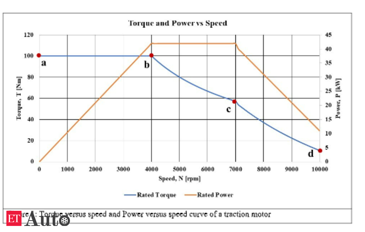
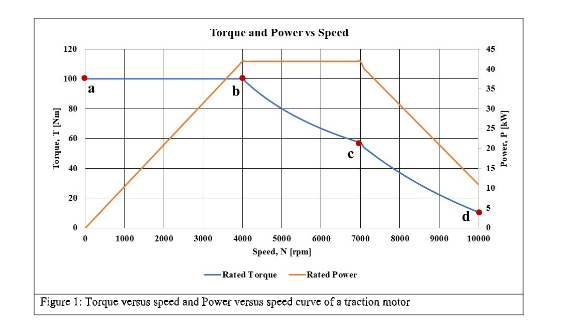
Within the second article, we mentioned the underlying rules of electrical motors. At this time we will focus on one of the crucial vital traits of the motors, area weakening. Subject weakening is an important idea enabling a motor to attain a large working vary, an important requirement for an EV motor. A typical torque versus pace and energy versus pace for an EV motor is proven in Determine 1. This determine reveals three areas of operation:
Area 1 (a to b): Fixed torque
Area 2 (b to c): Subject weakening
Area 3 (c to d): Deep area weakening
The idea of area weakening is greatest understood utilizing Maxwell’s stress tensor. The idea of Maxwell’s stress tensor entails intensive arithmetic, however the good half is that so much could be defined by graphical evaluation, and that is the method that we use within the following rationalization. We are going to prohibit our dialogue to Area 2 and focus on Area 3 within the subsequent article.
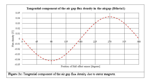
To know the concept of area weakening, start with a quite simple construction proven in Determine 2a. This construction has two ferromagnetic rings labelled as stator and rotor yokes. To the stator yoke, now we have glued a pair of magnets of alternate polarity. Within the air hole, we place a Corridor-effect sensor which strikes alongside a round path proven by the dotted circle. Because the sensor strikes alongside the trail and completes on rotation, it measures the flux density within the air hole. Since it’s a cylindrical construction, the flux density has radial and tangential parts. The measured flux densities are proven in Figures 2b and 2c. The magnitude of the radial element is far bigger than the tangential element due to the best way the magnets are magnetised.
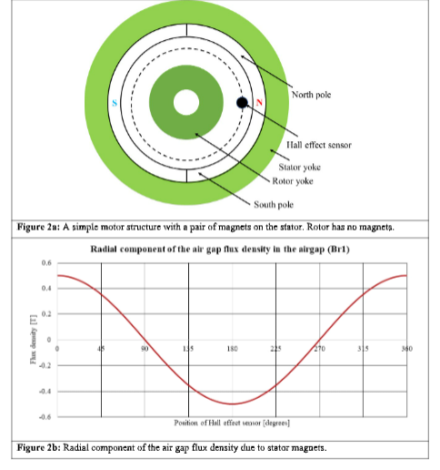
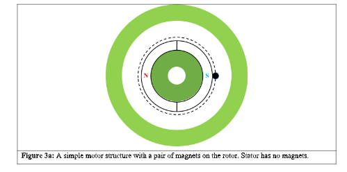
Equally, if we place a pair of magnets simply on the rotor, then we will get the air hole flux density within the air hole as proven in Determine 3. Figures 2 and three present that the Corridor-effect sensor begins from the identical place. In Determine 2 it sees the mid of the North Pole, whereas in Determine 3 it sees the mid of the South Pole, however the magnitude of the radial flux that it measures in each circumstances (Figures 2a and 3a) is optimistic as a result of the in each circumstances, the flux strains enter the sensor in the identical path.
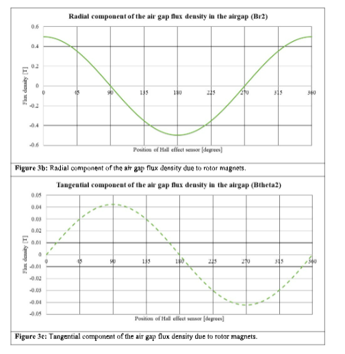
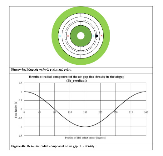
To date, now we have seen the flux density distribution for the stator and rotor in isolation, and issues are uneventful. The state of affairs turns into very fascinating after we place the magnets on the stator and rotor, as proven in Determine 4a. As quickly as now we have each units of magnets, the interplay between two magnetic fields occurs, and torque comes into existence. The magnitude of the torque is proportional to the relative place of the stator and rotor’s magnetic fields and the relative power between them.
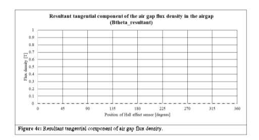
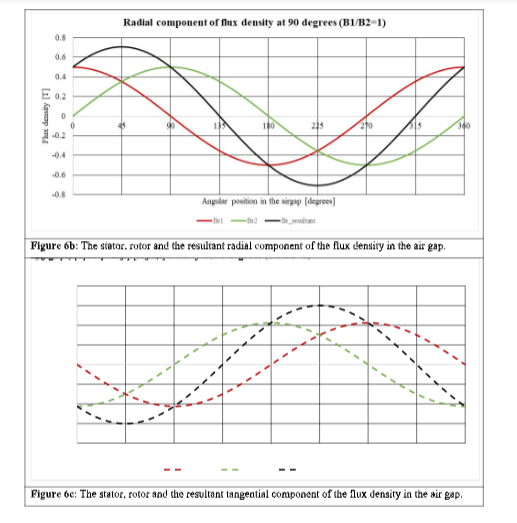
In Determine 4a, now we have a state of affairs the place the stator’s North Pole faces the rotor’s South Pole, and each the magnets are of equal power. The resultant radial and tangential parts of the magnetic flux density measured by the sensor are proven in Figures 4b and 4c. The radial flux densities of the stator and rotor support one another (Figures 2b and 2c), whereas the tangential parts are in antiphase to one another and cancel out (Figures 2c and 3c).
The torque in a motor is proportional to the multiplication of the radial and tangential magnetic flux densities:
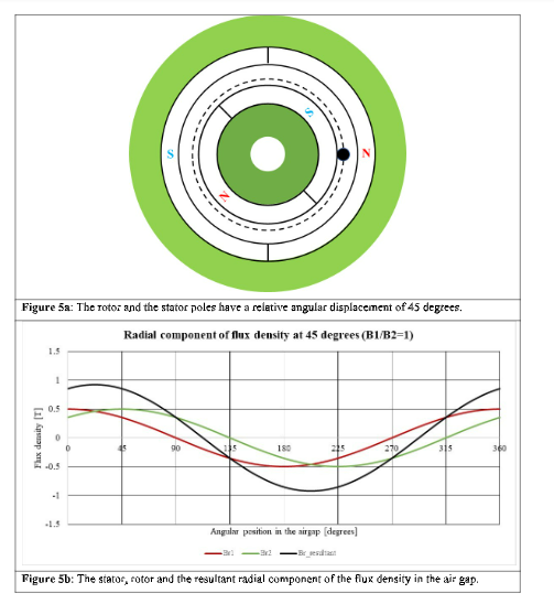
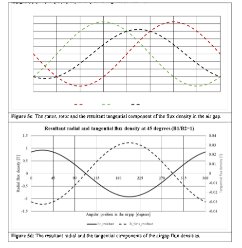
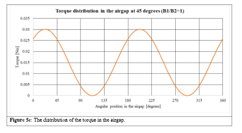
Because the tangential element is zero for the orientation proven in Determine 4a, the torque produced shall be zero. If the rotor is displaced by 45 levels, the tangential element shall be nonzero, and torque shall be produced, as proven in Figures 5a to 5e. Determine 5e is the distribution of the torque within the air hole periphery, and the summation of the values provides the entire torque at this place. The summation, on this case, is 108 Nm.
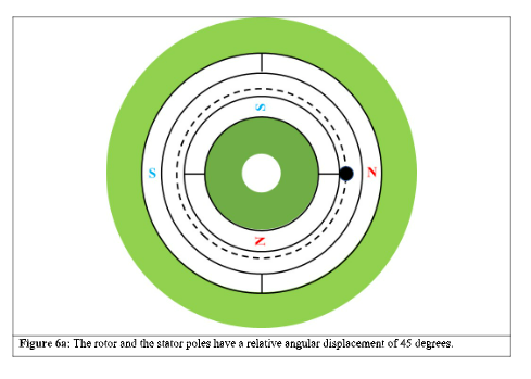
Equally, the state of affairs for the relative angle of 90 levels is proven in Figures 6a to 6e.
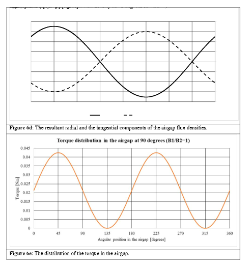
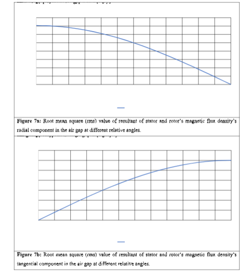
Suppose we do a whole evaluation from 0 to 180 levels relative angle between the stator and the rotor. In that case, the foundation imply sq. values of the radial, tangential and the resultant (vector sum of radial and tangential parts) present a reducing magnitude (Determine 7a to 7c). That is area weakening (additionally referred to as flux weakening).
The torque peaks at 90 levels as a result of, at that angle, the product of the radial and tangential parts is most. The whole torque versus the relative angle between the stator and the rotor magnets is proven in Determine 8.
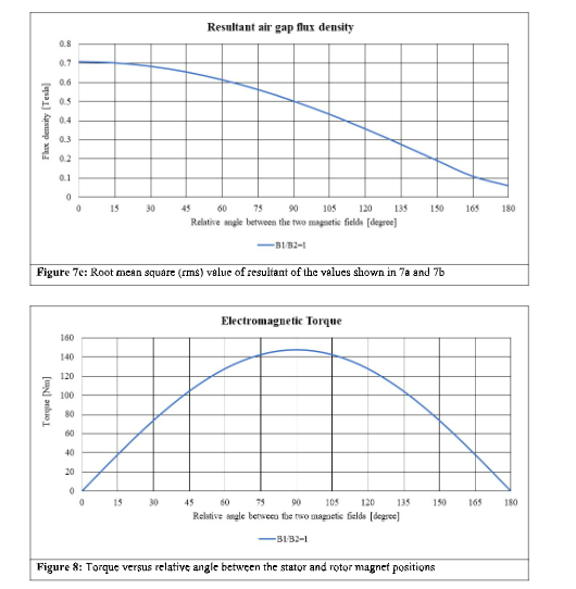
Now we return to Determine 1. In the complete area 1 (a to b), we hold the relative angle between the stator and rotor magnetic fields fixed (near 90 levels). Because the rotor pace will increase, we enter area 2 (b to c), we begin to improve the angle away from 90 levels, and the motor enters the sector, weakening the area. The selection of the relative angle with respect to hurry is the job of the management algorithm.
Within the subsequent article, we are going to proceed our dialogue on area weakening and discover some very fascinating outcomes and their implications within the design of motors. We will additionally see that the sector weakening functionality must be taken under consideration within the design part. Solely a correctly designed motor will allow area weakening.
(Dr. Ing Praveen Kumar is Professor, Division of Electronics and Electrical Engineering, IIT Guwahati. Views are private.)

